Valve material: forged steel A105 valve size: DN250 electric actuator: Multi-turn type voltage:480V
| Availability: | |
|---|---|
| Quantity: | |
forged steel gate valve with electric actuator
Multi-turn valve electric actuator, known by the name of Z-type, which is used for opening, closing or adjusting the valves, is an essential actuating device which can be used for remote control, centralized control and self control to the valves, with features of comprehensive function , reliable performance, advanced control system, small volume, light weight, convenient application and maintenance an so on .It can be applicable to the valves, whose open-close parts will move in a straight line, such as gate valve, stop valve, diaphragm valve, anchor gate, water gate valve and so on.. The actuator can be used in the industries like electric power, metallurgy, petroleum, chemical engineering, paper-making, sewage disposal and so on. There are many types for multi-turn electric actuator: outdoor type, explosion-proof type, integral type, integral-regulation type, integral explosion –proof type , integral-regulation explosion –proof type and so on .It can be divided into torque type and thrust type according to the connection type. The performance of the product shall conform to the specification in JB/T8528-1997 Technical Condition for Common Valve’s Electrical Devices. The performance of the explosion-proof product shall conform to the specifications in GB3836.1-2000 The Electrical Equipment used in Explosive Gas Atmosphere: the first part: General Rdquirements,GB3836.2-2000 The Electrical Equipment used in Explosive Gas Atmosphere: the second part: Explosion-proof type “d”, and JB/T8529-1997 Technical Condition for Explosion-proof Valve’s Electrical Devices. And it has passed the verification of National Quality Supervision & Testing Centre for Explosion-proof Electrical Products, and has got the Conformity Certificate of Protection of the whole series. And we have got the manufacturing license of industrial of industrial products approved by General Administration of Quality Supervision, Inspection and Quarantine.
Valve introduction
1.Body: A105+STL
2.Wedge: A105
3.Seat: A105+STL
4.Stem: 2Cr13
5.Bonnet:A105
6.Gasket Ring:304
7.Retainer:304
8.Bonnet Clamp:A105
9.Packings:Flex.graphite
10.Packing Spacer Ring: 304
11.Bonnet Nuts:2H
12.Bonnet Bolts: B7
13.Slotted Bolt Tray:A105
14.Bolts: B7
15.Slotted Bolt Tray:A105
16.Gland:13Cr
17.Gland Flange:A105
18:Slotted Nuts:2H
19. Slotted Bolt:B7
20. Electric Nut:D-2
21. Holder:WCB
22. Electric Actuator: Assembling Unit
| Size Speci- fication | A | B | C | D | E | F | G | φH | φI | φJ | K | L | M | φN | O | P | Q |
| PT18 | 165 | 268 | 358 | 230 | 119 | 41 | 11 | 457 | 101 | 229 | 265 | 30 | 179 | 217 | 253 | 233 | 87 |
| PT20/25 | 230 | 345 | 388 | 230 | 119 | 41 | 25 | 650 | 127 | 229 | 265 | 30 | 199 | 217 | 303 | 285 | 108 |
| PT35 | 247 | 368 | 402 | 230 | 120 | 42 | 40 | 786 | 151 | 229 | 307 | 30 | 222 | 217 | 341 | 315 | 122 |
| Size Speci- fication | A | B | C | D | E | F | G | φH | φI | φJ | K | L | M | φN | O | P | Q | R |
| PT70/90 | 335 | 521 | 503 | 230 | 175 | 35 | 61 | 432 | 178 | 438 | 358 | 30 | 272 | 217 | 60 | 517 | 384 | 140 |
| PT91 | 360 | 545 | 503 | 230 | 175 | 35 | 61 | 432 | 222 | 438 | 358 | 30 | 272 | 217 | 60 | 517 | 384 | 140 |
| PT95 | 335 | 521 | 503 | 230 | 175 | 35 | 61 | 432 | 178 | 438 | 358 | 30 | 272 | 217 | 60 | 517 | 384 | 140 |
Structure
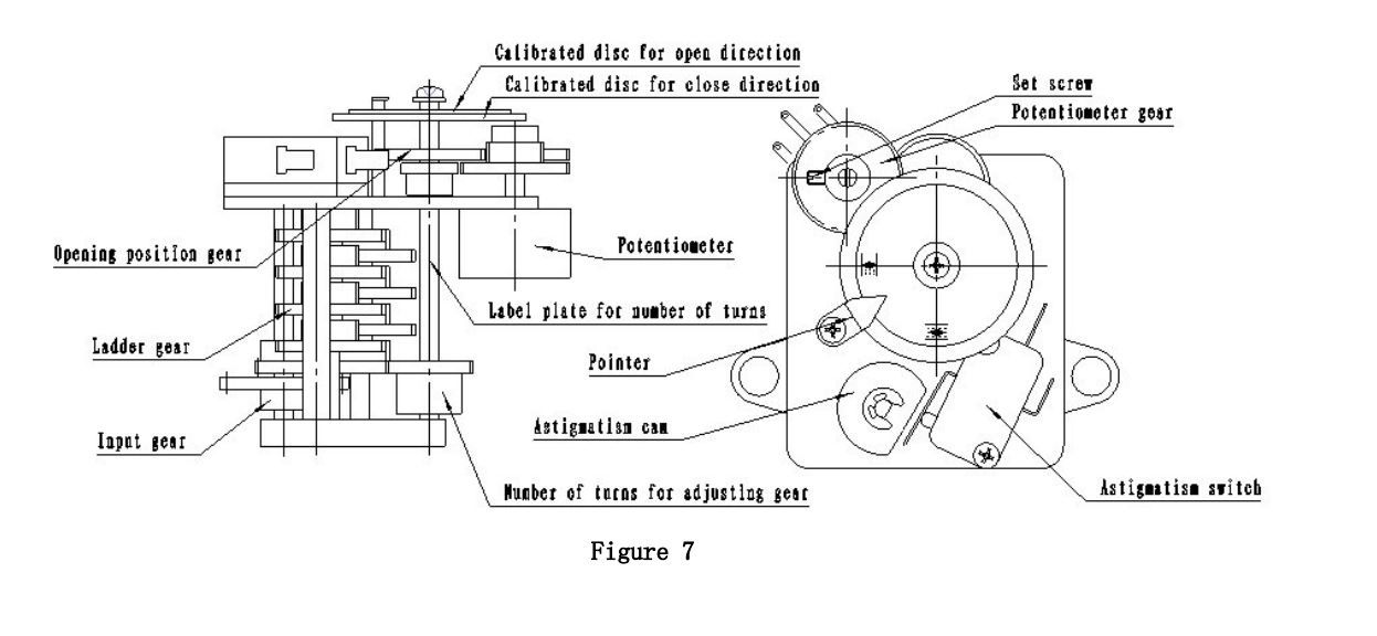
Z type electric actuator is consisted of motor, speed reducer, torque controller, motion controller, opening position indicator, manual-electric shifter, hand wheel and electric parts. The conventional type is sealing with ground surfaces; the outdoor type applies the round rabbet and o-seal ring seal; The explosion-proof type has the same sealing structure as the outdoor type, is added by the explosion-proof surface, and applies explosion-proof type connecting box and three phase motor used for the outdoors, anti corrosion, explosion-proof type electric valve of the YBDF series. The transmission principal is shown on Figure 4.
5.1 Motor: The outdoor type applies the YDF type, the explosion-proof type applies the three phase asynchronous motor dedicated for the YBDF type valve.
5.2 Speed reducer: it is consisted of one pair of spur gear and worm gear. The motive power of motor is transmitted to the output axis through the speed reducer.
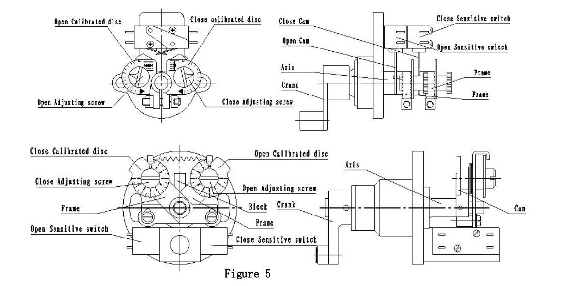
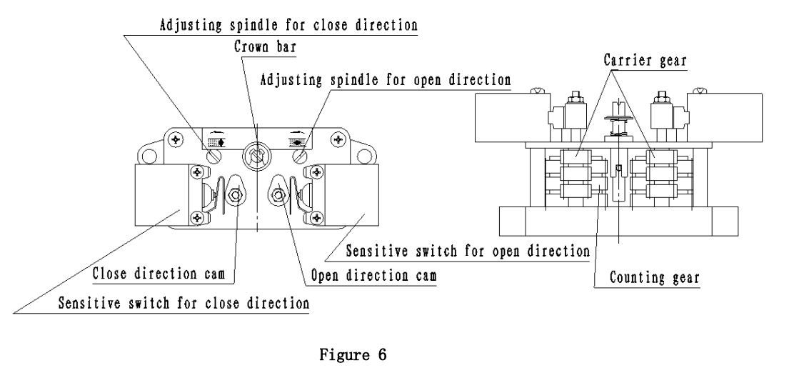
5.3 Torque controller: The torque controller is divided into the outdoor type and explosion–proof type. Refer to Figure 5 for the structure.
5.3.1The outdoor type series: when the output axis is subject to some torque, besides the rotation, the worm also generates the axial displacement and drives the crank. During the crank movement, it drives the axis and cam to compress the sensitive switch to cut off the motor power and stop the motor rotation. In this way, the output torque of the electric actuator is controlled to protect the electric valve.
5.3.2The explosion-proof type: When the output axis is subject to a certain torque, besides the rotation, the worm also generated the axial displacement and drives the crank to make the block generate the angular displacement, to compress the cam to uplift the bracket. When the torque on the output axis increases to the setting torque, the bracket is uplifted until the sensitive switch moves to cut off the motor power and stop the motor rotation. In this way ,the output torque of the electric actuator is controlled to protect the electric valve


Manual-Electric shifter It is the semi automatic switch with its structure referring to the Figure 8, which consists of handle, cam frame, upright rod, middle clutch, compressed spring and so on. When operating with handle, first push the switch handle to the position of manual operation, the cam will turn together with the handle axis, which will make the frame supporting on the cam surface be uplifted, and at the same time, the middle clutch, which is on the frame ,and can make axial movement on the output axis, will be uplifted too , and compress the compressed spring .When the handle is pushed to certain position , the middle clutch will disengage with worm wheel, whereas it will engage with hand wheel, and then the acting force on the hand wheel will be transmitted to the output axis through the middle clutch , which turns into the manual operation state. When the frame is uplifted to a certain height, under the action of torsion spring, the upright rod fixed to the frame will stand erect on the end face of the worm wheel to support the frame in order to make the middle clutch not fall down. After pushed to the manual operation position, the handle can be released, and then carry on the operation with hand wheel. When the motor drives the turning of the worm wheel, the upright rod will come to the ground, and the middle clutch will move towards the direction of worm wheel rapidly, and engage with worm wheel, at the same time disengage with the hand wheel, which turns into the electric state.(when using manual switching , if you can not switch to the manual position, please switch over the handle and at the same time turn the hand wheel.)
forged steel gate valve with electric actuator
Multi-turn valve electric actuator, known by the name of Z-type, which is used for opening, closing or adjusting the valves, is an essential actuating device which can be used for remote control, centralized control and self control to the valves, with features of comprehensive function , reliable performance, advanced control system, small volume, light weight, convenient application and maintenance an so on .It can be applicable to the valves, whose open-close parts will move in a straight line, such as gate valve, stop valve, diaphragm valve, anchor gate, water gate valve and so on.. The actuator can be used in the industries like electric power, metallurgy, petroleum, chemical engineering, paper-making, sewage disposal and so on. There are many types for multi-turn electric actuator: outdoor type, explosion-proof type, integral type, integral-regulation type, integral explosion –proof type , integral-regulation explosion –proof type and so on .It can be divided into torque type and thrust type according to the connection type. The performance of the product shall conform to the specification in JB/T8528-1997 Technical Condition for Common Valve’s Electrical Devices. The performance of the explosion-proof product shall conform to the specifications in GB3836.1-2000 The Electrical Equipment used in Explosive Gas Atmosphere: the first part: General Rdquirements,GB3836.2-2000 The Electrical Equipment used in Explosive Gas Atmosphere: the second part: Explosion-proof type “d”, and JB/T8529-1997 Technical Condition for Explosion-proof Valve’s Electrical Devices. And it has passed the verification of National Quality Supervision & Testing Centre for Explosion-proof Electrical Products, and has got the Conformity Certificate of Protection of the whole series. And we have got the manufacturing license of industrial of industrial products approved by General Administration of Quality Supervision, Inspection and Quarantine.
Valve introduction
1.Body: A105+STL
2.Wedge: A105
3.Seat: A105+STL
4.Stem: 2Cr13
5.Bonnet:A105
6.Gasket Ring:304
7.Retainer:304
8.Bonnet Clamp:A105
9.Packings:Flex.graphite
10.Packing Spacer Ring: 304
11.Bonnet Nuts:2H
12.Bonnet Bolts: B7
13.Slotted Bolt Tray:A105
14.Bolts: B7
15.Slotted Bolt Tray:A105
16.Gland:13Cr
17.Gland Flange:A105
18:Slotted Nuts:2H
19. Slotted Bolt:B7
20. Electric Nut:D-2
21. Holder:WCB
22. Electric Actuator: Assembling Unit
| Size Speci- fication | A | B | C | D | E | F | G | φH | φI | φJ | K | L | M | φN | O | P | Q |
| PT18 | 165 | 268 | 358 | 230 | 119 | 41 | 11 | 457 | 101 | 229 | 265 | 30 | 179 | 217 | 253 | 233 | 87 |
| PT20/25 | 230 | 345 | 388 | 230 | 119 | 41 | 25 | 650 | 127 | 229 | 265 | 30 | 199 | 217 | 303 | 285 | 108 |
| PT35 | 247 | 368 | 402 | 230 | 120 | 42 | 40 | 786 | 151 | 229 | 307 | 30 | 222 | 217 | 341 | 315 | 122 |
| Size Speci- fication | A | B | C | D | E | F | G | φH | φI | φJ | K | L | M | φN | O | P | Q | R |
| PT70/90 | 335 | 521 | 503 | 230 | 175 | 35 | 61 | 432 | 178 | 438 | 358 | 30 | 272 | 217 | 60 | 517 | 384 | 140 |
| PT91 | 360 | 545 | 503 | 230 | 175 | 35 | 61 | 432 | 222 | 438 | 358 | 30 | 272 | 217 | 60 | 517 | 384 | 140 |
| PT95 | 335 | 521 | 503 | 230 | 175 | 35 | 61 | 432 | 178 | 438 | 358 | 30 | 272 | 217 | 60 | 517 | 384 | 140 |
Structure
Z type electric actuator is consisted of motor, speed reducer, torque controller, motion controller, opening position indicator, manual-electric shifter, hand wheel and electric parts. The conventional type is sealing with ground surfaces; the outdoor type applies the round rabbet and o-seal ring seal; The explosion-proof type has the same sealing structure as the outdoor type, is added by the explosion-proof surface, and applies explosion-proof type connecting box and three phase motor used for the outdoors, anti corrosion, explosion-proof type electric valve of the YBDF series. The transmission principal is shown on Figure 4.
5.1 Motor: The outdoor type applies the YDF type, the explosion-proof type applies the three phase asynchronous motor dedicated for the YBDF type valve.
5.2 Speed reducer: it is consisted of one pair of spur gear and worm gear. The motive power of motor is transmitted to the output axis through the speed reducer.
5.3 Torque controller: The torque controller is divided into the outdoor type and explosion–proof type. Refer to Figure 5 for the structure.
5.3.1The outdoor type series: when the output axis is subject to some torque, besides the rotation, the worm also generates the axial displacement and drives the crank. During the crank movement, it drives the axis and cam to compress the sensitive switch to cut off the motor power and stop the motor rotation. In this way, the output torque of the electric actuator is controlled to protect the electric valve.
5.3.2The explosion-proof type: When the output axis is subject to a certain torque, besides the rotation, the worm also generated the axial displacement and drives the crank to make the block generate the angular displacement, to compress the cam to uplift the bracket. When the torque on the output axis increases to the setting torque, the bracket is uplifted until the sensitive switch moves to cut off the motor power and stop the motor rotation. In this way ,the output torque of the electric actuator is controlled to protect the electric valve


Manual-Electric shifter It is the semi automatic switch with its structure referring to the Figure 8, which consists of handle, cam frame, upright rod, middle clutch, compressed spring and so on. When operating with handle, first push the switch handle to the position of manual operation, the cam will turn together with the handle axis, which will make the frame supporting on the cam surface be uplifted, and at the same time, the middle clutch, which is on the frame ,and can make axial movement on the output axis, will be uplifted too , and compress the compressed spring .When the handle is pushed to certain position , the middle clutch will disengage with worm wheel, whereas it will engage with hand wheel, and then the acting force on the hand wheel will be transmitted to the output axis through the middle clutch , which turns into the manual operation state. When the frame is uplifted to a certain height, under the action of torsion spring, the upright rod fixed to the frame will stand erect on the end face of the worm wheel to support the frame in order to make the middle clutch not fall down. After pushed to the manual operation position, the handle can be released, and then carry on the operation with hand wheel. When the motor drives the turning of the worm wheel, the upright rod will come to the ground, and the middle clutch will move towards the direction of worm wheel rapidly, and engage with worm wheel, at the same time disengage with the hand wheel, which turns into the electric state.(when using manual switching , if you can not switch to the manual position, please switch over the handle and at the same time turn the hand wheel.)
